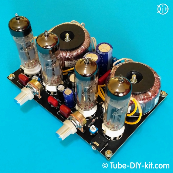
Electronic DIY kit: Tube SRPP stereo low frequency amplifier for computer
A four-tube, two-stage stereo low-frequency amplifier is designed for high-quality reproduction of signals from computer audio cards, smartphones and tablets on inexpensive computer speakers. Current consumption: The board size: 125 x 80 mm
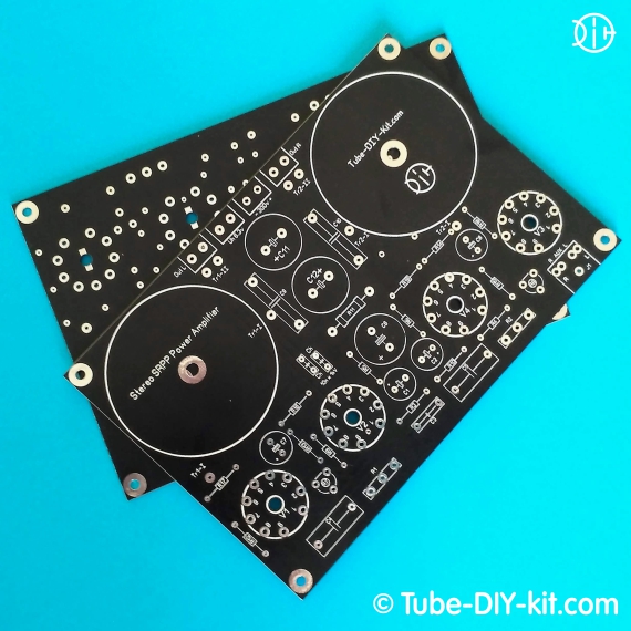
The kit comes in the form of a printed circuit board
The kit does not contain scarce parts and winding units. As the output, standard 220/12V transformers with a ~15w overall power were used.
When developing this amplifier, we set out to create a device that does not depend on the parameters of the output transformer, which is the most expensive and inaccessible part of a tube amplifier. Often the cost of the output transformer is equal to or even more expensive than the device. And in a stereo amplifier, this amount must be multiplied by 2. The parameters of inexpensive NOS transformers and their limited availability for a fan of tube sound did not add optimism either. And we decided to double the number of inexpensive tubes and assebly an amplifier with good parameters on standard transformers as a output. We are presenting to your what we did.
Regards, Developers
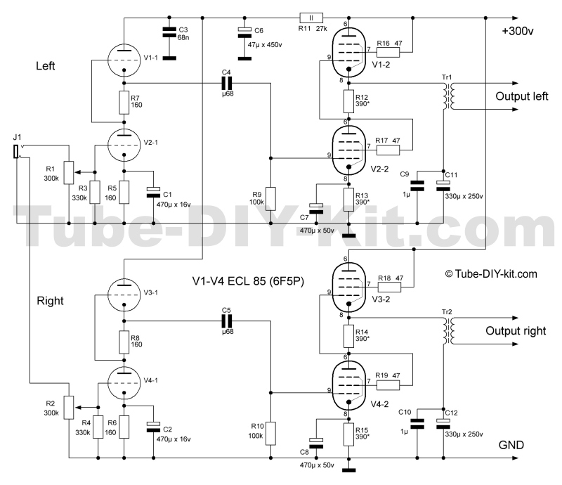
Circuit, instructions for assembling and tuning a tube SRPP stereo low frequency amplifier for computer:
 Install on the board and solder the parts according to the circuit diagram and the layout of the board. Pay special attention to the correct connections of the transformer windings to the board. We strongly recommend installing electrolytic capacitors under the board, carefully observing their polarity. 4 tubes create a fairly strong flow of infrared radiation and the elements above the board are heated. If the capacitors are mounted on top, then put the resistor R11 on the bottom, and vice versa. R11 is also heated quite strongly, so it is advisable to choose its power at 5 watts.
An artificial midpoint cannot be used in this amplifier, since the voltage limit between the cathode and the heater for 6F5P lamps should not exceed 100V. Therefore, only floating heating - without connection to the ground! The filter capacitors marked on the board as Ch are not indicated on the circuit and are recommended for installation when the amplifier is working with extraneous power supplies. In our power supplies, such capacitors are already installed. Under the tube sockets, on the board, there are unconnected spots for fans of tube lighting. They can solder LEDs and organize their power supply from heater circuits.
A properly assembled amplifier does not need to be tuned. It is recommended, after assembly, to check the current consumption during the first start-up. It should not exceed 80mA. The normal consumption of the amplifier is about 70-75mA, which provides a relatively soft mode of operation of the tubes and their increased durability. Next, check the voltage at the cathodes of the tubes V1-2 and V3-2. They should be approximately equal to half the anode voltage. If necessary, the currents of the output stages are regulated by cathodic resistors R12, R13, R14 and R15.
During development, this amplifier was powered from our own power supply. The AC noise was not audible. The need for stabilization of the anode and/or heating voltages is not noted. But we can not guarantee that there will be no noise 50Hz when using an external power supply.
Experiments with output transformers showed that the best results were achieved with 220/12V toroidal transformers (for speaker in the 8 ohm) and overall power from 15W, but the amplifier behaved quite adequately with heating transformers TN series. Such transformers are not expensive and are not in short supply. The main condition is that the overall power should exceed the output by 8-10 times. The use of SE output transformers is not recommended - the magnetic gap decently spoils the sound picture.


