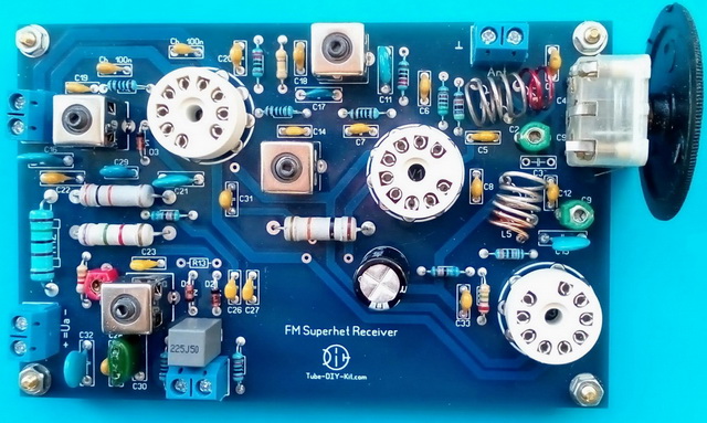
Radio DIY kit: Radio-frequency unit FM superheterodyne receiver on 3 vacuum tubes
The high-frequency FM superheterodyne unit together with an external low-frequency amplifier provides a reception of local FM radio stations with a frequency modulation. Current consumption: The board size: 131 x 91 mm.
The set is supplied as a printed circuit board and a kit of parts.
It is possible to purchase the set without the 6F12P, 6K13P (EF183), EM87 (6E2, EM87) vacuum tubes.
 |
 |
Instructions for assembling and tuning the device:
Install and solder all the parts on the board except the R6 resistor according to the circuit diagram and the board markup. Make sure the electrolytic capacitors are installed in the right polarity. The filter capacitors marked on the board as Ch are not indicated on the scheme but are recommended to be obligatorily installed in this radio constructor. The V3 lamp and its strapping C29, C31, C33, D3, R17, R18, R19 and R20 do not have to be installed obligatorily. They are used only for indication.

The L3, L6, L7, L8, and L9 coils you have to reel on the frames supplied with the kit. The L3, L6, L7 have 12 turns in two sections by 6. L8 has 3 turns in a separate section over the L7. The L9 has 6+6 turns in 2 middle sections retracted from the middle. Some coils can be substituted by standard (typical) intermediate-frequency (IF) coils from transistors FM receivers. L3, L6, L7, and L8 can be substituted by the orange IF coils. With some deterioration L6 can use a lilac one coil. L9 can use a violet one (but not any, it should fit the board). If typical IF coil are installed, the C7, C14, C19, and C23 capacitors do not have to be installed.
The input and heterodyne coils you have to reel by the 1mm diameter cable that is included in the kit and contain 1.75 turns in L1, 4.75 turns in L2, 3.75 turns in L4, 1.75 turns in L5 on a mandrel with a diameter of 7 mm. THe coils must be placed mutually as shown in the photo. If it is not done you risk getting a heterodyne that does not launch or an converter self-excitation.
After assembling the scheme, a properly assembled intermediate-frequency tract starts working at once but a coils tuning is required. To do this insert the V2 and V3 lamps into the panels, connect unit to the low-frequency amplifier block input and energize the board with the anode and heater voltages from the power supply. Now we need a signal with a frequency of 10.7 MHz. If you have a standard signal generator or an NWT then you know what to do. If not, you need any receiver with the same IF - 10.7Mhz. Find the output IF coil on the board of the reference receiver and connect its "hot" end with the V1 tube socket pin#3 through a small capacity (3-5pf). Now turn on both devices and achieve the maximum strip convergence of the V3 tube by turning the coils cores. If possible, tune the frequency detector. To do this, connect the voltmeter parallel to the C28 capacitor. Then turn the L9 core and change the C24 trimmer capacity in order to achieve the loudest and clearest sound while the voltmeter indicators are as close as possible to 0.
Then turn off the reference receiver, solder the R6 on the board and insert the V1 lamp. Connect a piece of the cable as an antenna to the “Ant” kernel. Make sure that the antenna signal gets through the C1 capacitor to the L2 coil. Solder the jumper on the board. Turn on the receiver and tune to any radio station. It should work without any problems.
Shifting and pushing apart the turns of the heterodyne L4 coil set the low-frequency range border and with the help of the tuning capacitor in the C10 board body set the high-frequency border. If the C10 capacity is not enough to engage the whole diapason or on the contrary the diapason is too big then use the C9 trimmer to set the engagement you want.
Solder the jumpers so that the signal from the antenna would get to L1. Now by shifting and pushing apart the L2 turns achieve the highest V3 lamp strip convergence when tuning for a low-frequency radio station. With the help of a tuning capacitor in the C4 board body and the C2 trimmer achieve the same result but in the high-frequency part of the diapason.
All that is left is trying out all the variants of connecting the antenna and deciding which one is better to stop with. Using the jumpers you have a possibility to connect the antenna symmetrically, asymmetrically, directly to the coil L2.