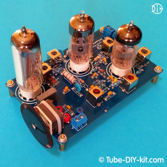
Radio DIY kit: Radio-frequency unit AM superheterodyne receiver on 3 vacuum tubes
A medium-wave high-frequency AM superheterodyne unit together with an external low-frequency amplifier provides reception of local and far-away powerful AM radio stations on the external antenna. Current consumption: The board size: 131 x 91 mm.
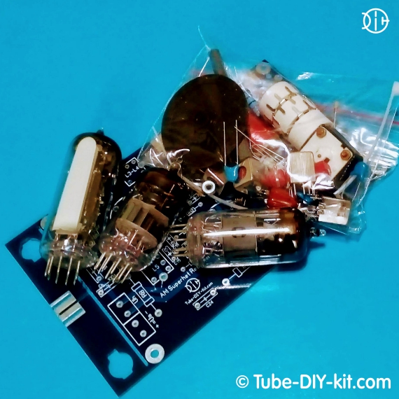
The set is supplied as a printed circuit board and a kit of parts.
It is possible to purchase the set without the 6F12P, 6K13P (EF183), EM87 (6E2, EM87) vacuum tubes.
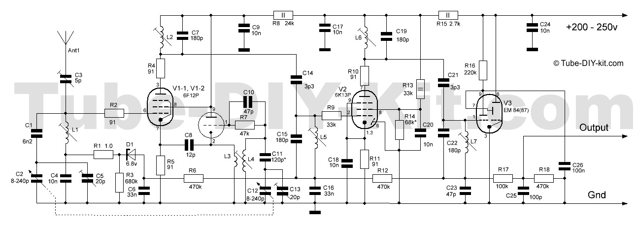
Circuit, instructions for assembling and setting of radio-frequency unit AM superheterodyne receiver:
Cut off the main board brackets. They will be required to mount the ferrite antenna. Install the board and solder the details according to the scheme and board marking except the R8 resistor. Make sure the polarity is right when installing the electrolytic capacitors. The filter capacitors marked on the board as Ch are not indicated on the scheme but are recommended to be obligatorily installed in this radio constructor.

If only generic coils that are supplied by the set are installed, the C7, C15, C19, and C22 capacitors should not be installed. We recommend using a ferrite (magnetic) antenna (MA) only in a zone of reliable signal reception of powerful local radio stations. In all other cases, you should use in reception input circuits a typical red shielded coil that is supplied with the set. We should notice that tuning and using a receiver with an MA is more difficult than with a shielded coil in the input. The spurious connection between the IF circuits and the MA in the low-frequency part of the diapason will have to be compensated by decreasing the gain on the IF cascade (by decreasing the nominal R14).
If you have decided to use the MA after assembling the scheme then insert the brackets into the board end and solder them. Insert the kernel of the magnetic antenna in the holes of the brackets and solder the coils of the MA in the L1 holes.
A properly assembled IF tract starts working at once but requires coils tuning. To do this, insert the V2 and V3 tubes in the panels, connect them to the input of the low-frequency amplifier and energize the board with the anode and heater voltage from the power supply. Now we need a 455 kHz frequency signal. If you have got a standard signal generator or an NWT then you already know what to do. If not, you need any receiver with the same IF 455kHz. Find the output IF coil on the board of the reference receiver and connect its "hot" end with the V1 tube socket pin#3 through a small capacity (3-5pf). Now turn on both devices and achieve the maximum strip convergence of the V3 tube by turning the coils cores.
Then turn off the reference receiver, solder the R8 on the board and insert the V1 tube. Connect the antenna to the "Ant" terminal. Make sure that the antenna signal gets through the C1 capacitor to the L1 coil. Solder the jumper on the board. Turn on the receiver and tune to any radio station. It should work without any problems.
By turning the core of the heterodyne L3-4 coil set the low-frequency diapason border. Do the same with the C13 trimmer but for the high-frequency border.
Then by turning the core (moving the MA coil on the rod) maximize the strip convergence in the V3 lamp while tuning for a low-frequency station. With the C5 trimmer do the same thing for the high-frequency diapason. Repeat this procedure 2-3 times.
All that is left is trying out all the variants of connecting the antenna and deciding which one is better to stop with. Find the best combination for your antenna by soldering the jumpers on the board.
* You need at least a room antenna! It is better if it is an external one. The good results were obtained from the Mini Whip antenna.


