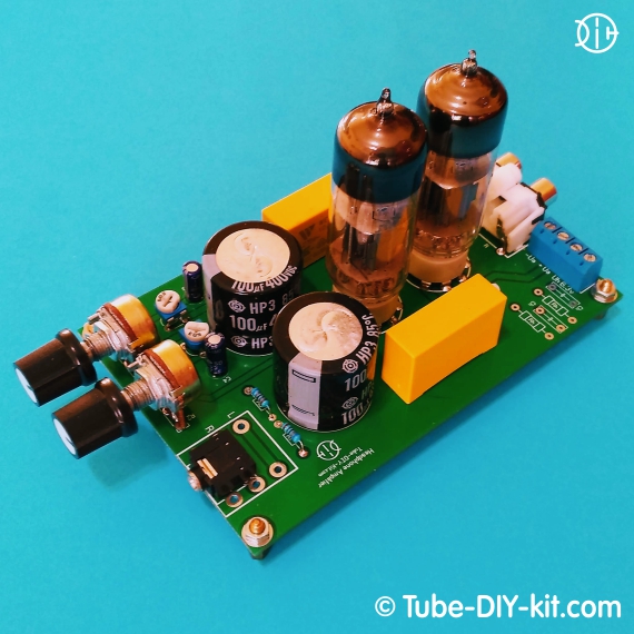
Electronic DIY kit: Dual-tube SRPP Stereo Low Frequency Headphone Amplifier
High-quality, simple and reliable SRPP Low Frequency Amplifier for Headphones. Current consumption: The board size: 125 x 80 mm
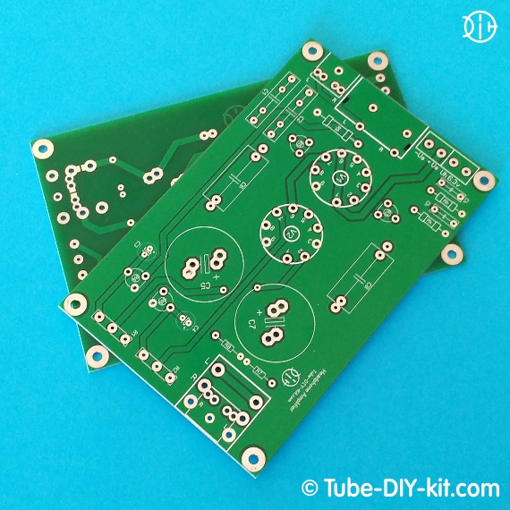
The kit comes in the form of a printed circuit board
The kit does not contain scarce parts and winding units
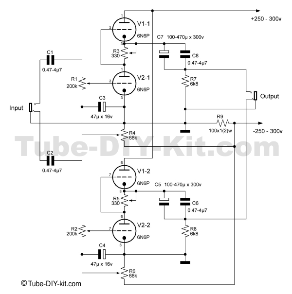
Circuit, instructions for assembling and tuning a dual-tube SRPP stereo low-frequency amplifier for headphones:
Install on the board and solder the parts according to the circuit diagram and the layout of the board. Observe polarity when installing electrolytic capacitors. The filter capacitors marked on the board as Ch are not indicated on the diagram and are recommended for installation when the amplifier is working with extraneous power supplies. In our power supplies, such capacitors are already installed. If desired, you can organize an artificial midpoint in the incandescent chains. To do this, the board provides mounting locations for resistors Rh. Their resistance is approximately 300 ohms to 3 kilo-ohms.
 The design provides the ability to access the headphones through Jack 3.5 or 6.35mm. When choosing any of the methods, it will be necessary to soldering one of the two jumpers on the board under the output connector.
After assembling the amplifier, connect the power supply to the power terminals of the amplifier and install only the V2 tube (the lower one according to the diagram) in the socket. Do not connect headphones; volume controls are at minimum. Trim resistors R4 and R6 in the lower position according to the scheme. In the socket of the tube V1, between the slots 1 and 3, 6 and 8, respectively (anodes and cathodes), insert a 5.6 - 6.2k resistor on a two-watt resistor. Now you can supply power to the amplifier, controlling the currents of the anodes of the V2 triodes. The total current of the anodes should not exceed 50mA. Then, measure the current of one channel (anode) and set it with the resistor R4 (R6) at about 25-30mA, and repeat the procedure with the second channel, achieving equal currents of the anodes V2.
The next step is to remove the resistors between the cathodes and anodes of the V1 tube and install it in place. The resistor motors R3 and R5 are set to the upper position according to the scheme. We supply power and measure the voltage at the cathodes V1. Resistors R3 and R5 set approximately half the supply voltage. Please note that under load, the anode voltage on the power supply will drop somewhat. Repeat this process several times, monitoring the total anode voltage.
Measure the total current consumption - it should not exceed 60mA. And better if you initially set it to about 20-25mA per channel. The volume will be more than enough for you, and the tubes in this mode will live much longer. Now you can apply a useful signal to the amplifier input and connect headphones. With the volume controls, set an acceptable gain level and balance the channels at the same volume level.
And a few comments from the developers:
- We did not notice a difference when using more affordable 6N6P-I tubes instead of 6N6P.
- During development, this constructor was powered from our own power supplies - simple and rectifier . In both cases, the noise of the alternating current was practically not audible. The need for stabilization of the anode and/or heating voltages is not noted. It was not even necessary to create an artificial midpoint with Rh resistors; the built-in EMI filter and Ch capacitors were quite enough. But we can not guarantee that there will be no noise 50Hz when using an external power supply.
- Remember that you can not connect the mass of the amplifier with a minus of the anode voltage. Otherwise, the negative bias from R9 will no longer be fed to the lower tube and it will enter supercritical mode with unpleasant consequences.
We hope you do not need to be reminded that all device connections during the setup process must be done with the power off and the capacitors discharged in the anode circuits.


