Radio DIY kit: AM superheterodyne receiver on two vacuum tubes
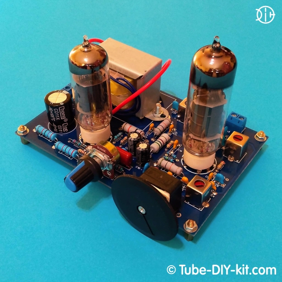
The medium-wave single-board, dual-tube AM superheterodyne provides the reception of local and long-range powerful AM radio stations to an external antenna. Current consumption: The board size: 131 x 91 mm.
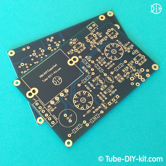
The kit comes in the form of a printed circuit board and a set of coils.
Possible purchase with 6I1P (ECH81), 6F4P(ECL84) tubes.
In this receiver, you will immediately get acquainted with several not-so-standard superheterodyne nodes. Firstly, it is a converter with a combined local oscillator on the heptode part of the V1 tube. Secondly, it is a regenerative detector on the triode part of V1. All together, it was possible to create the RF path of the superheterodyne receiver with the AGC with just one combined tube. Thirdly, it is a low frequency amplifier, with one cascade of voltage amplification and a powerful output cathode follower. This is possible because the regenerative detector provides pre-amplification by low frequencies. A cathode follower allows you to do without a tube output transformer with a gap. As such, a typical 220/9V transformer is used here. In general, the sum of technologies has led to the creation of a simple and original receiver with good sensitivity and selectivity.
Regards, Developers
Circuit, instructions for assembling and setting of dual-tube AM superheterodyne:
Install on the board and solder all parts except capacitors C5, C8-C10 according to the circuit diagram and the layout of the board. Observe polarity when installing electrolytic capacitors. Anti-noise capacitors marked on the board as Ch are not indicated on the circuit and are recommended for mandatory installation in this radio kit.

In the case of installation of the typical 455kHz coils, complete with the kit, capacitors C7 and C16 are not needed. Next, without inserting the V1 tube into the socket, turn on the receiver and check the operation of the low frequency amplifier. It is recommended, during the first start-up, to check the current consumed by the anode circuits. It should not exceed 20mA.
The next step is to install the V1 tube in the socket and instead of C5 connect the antenna to its grid through a 50-100pF capacitor. At this stage, rotating the cores of the coils L3, L5-L6 and changing the position of the R8 resistor, achieve the maximum level of ether noise by bringing the regenerative detector almost to generation. The intermediate frequency will be in the range of 400-500kHz, which is quite satisfactory. If R8 has reached the stop but there is still no generation, change its nominal value, for example, to 200 ohms. This happens when the tube V1 was in use or has a small gain.
Then, solder into the board C5 and C8-C10. Connect the antenna to the Ant terminal. Make sure that the signal from the antenna passes through capacitor C4 to coil L1. To do this, solder the jumper on the board. Turn on the receiver and rotate the core L1-L2 to listen ether noise. You should be able to do this without any problems. Now, by rotating the C2,C12 shaft and adjusting L1-L2, you can search for a working radio station. When tuned in, turn on another medium-wave receiver nearby and look for the signal from your local oscillator. The difference between the frequency of the local oscillator and the radio station will be your intermediate frequency.
By turning the core of the heterodyne L4 coil set the low-frequency diapason border. Do the same with the C13 trimmer but for the high-frequency border.
Further, rotating the core L1-L2, achieve the maximum volume level when tuning to a low-frequency station. A trimmer C3 achieve the same in the high-frequency part of the range. Repeat 2-3 times this procedure.
It remains only to try the antenna connection options and decide which one to stop at. Find the best combination for your antenna by fusing the jumpers on the board with solder and changing the capacitance of the C4 capacitor from 5pF when directly connected to the L2 coil to 1000pF when connecting the antenna through the L1 coupling coil.
The sensitivity of the receiver can be increased even more by blocking the operation of the AGC by installing a resistor R * with a nominal value of about 1M on the board.
* You need at least a room antenna! It is better if it is an external one. The good results were obtained from the Mini Whip antenna.


