DIY radio kit: Two vacuum tubes medium wave AM tuned RF receiver with a grid or regenerative detector
The two vacuum tubes radio receiver 0-V-1 provides a loud-speaking signal reception from local and far-away powerful radio stations by the external antenna. Current consumption: The board size: 131 x 91 mm.
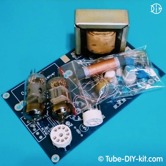
The set is supplied as a printed circuit board and a kit of parts.
It is possible to purchase the set without the 6K13P (EF183), 6J52P (E810F, 6J11P) vacuum tubes and/or the output transformer.
Instructions for assembling and tuning the device:
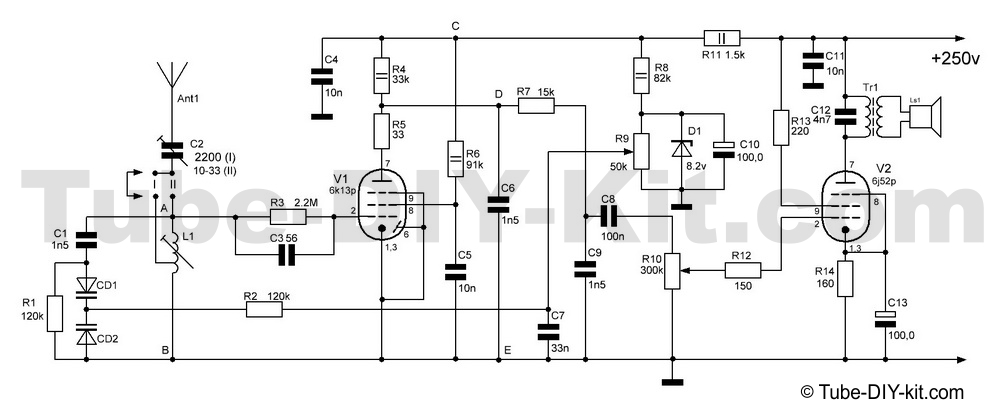
The optional kit allows you to assemble a radio receiver with a grid (Fig. 1) or regenerative (Fig. 2) detector. We recommend trying both variants and choosing the best one for your signal conditions. While assembling the variant with the grid detector you can use a typical heterodyne circuit (red-colored) from the transistor receiver in the L1 slot on the board instead of the ferrite antenna. In this way, a variety of input circuits and connections of the antenna with the circuit will be available. Try it out, find the best combination and install the C2 capacitor in the appropriate place (C2, C2’ or C2’’).
By default, the tube 6J52P (6J11P) is supplied in the construction set but it is possible to use an E810F tube instead. To do this you need to remove the pin #6 from the tube panel in a way to exclude contact with the board.
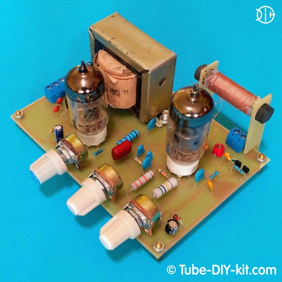
Cut off the main board brackets. They will be required to mount the ferrite antenna. Install the board and solder the details according to the scheme and board marking. While installing the electrolytic capacitors make sure the polarity is right. The filter capacitors marked on the board as Ch are not indicated on the scheme but are recommended to be installed if the receiver works with extraneous power supplies. In our power supplies, such capacitors are already installed.

pic. 1
After assembling the circuit, insert the brackets into the board end and solder them there. Install the kernel of the magnetic antenna in the holes of the brackets and solder the MA coils. After assembling the circuit, connect a anode and heater voltage from the power supply. According to the experience of assembling a few kits, a properly assembled radio constructor works at once, but it needs some tuning. It is recommended, during the first start-up, to check the current consumed by the anode circuits. It should not exceed 35mA. In case of exceeding this level of consumption pick denomination R14.
Wait until it gets dark - the medium-wave diapason will be available. Connect the "Ant" antenna to the terminal. Turn the potentiometer of the R9 tuning the leftmost position. Moving the magnetic antenna coil on the rod (turning the input coil core) and try to accept stations in the lower part of the range. Сhecking it with the monitoring receiver. If everything is done properly, the higher part of the diapason will be set automatically.
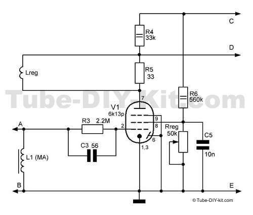
It is possible to improve the sensitivity and selectivity of the receiver by using a regenerative detector. To do this, referring to pic. 2, soldering the jumper spacing on the board, solder the communication coil to the Lreg holes, replace the R6 resistor and install the Rreg potentiometer in place.

pic. 2
By switching on and turning the Rreg clockwise you will hear either the increase or decrease of the noise. If the noise decreases then change swap the Lreg coil leads. Moving the magnetic antenna coil on the rod as described higher, set the receiver in the diapason. Here the setting is over but you can still experiment with the receiver by, for example, trying to tune it for short waves.
* An external antenna is required! You can use a Mini Whip antenna instead.


