Radio DIY kit: AM modulator and low power transmitter on vacuum tube
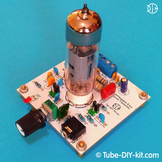
Low-power amplitude-modulated radio transmitter for local broadcasting in a limited radius from an arbitrary signal source Current consumption: The board size: 71 x 71 mm.
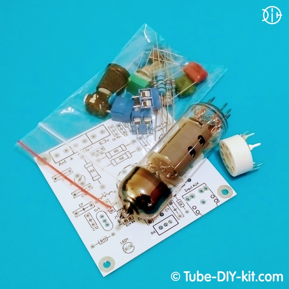
The set is supplied as a printed circuit board and a kit of parts.
It is possible to purchase the set without the 6I1P (ECH81) tube.
Instructions for assembling and tuning the device:
By default, the 6I1P (ECH81) tube is supplied in the set but it is possible to use the ECH84 tube. To do this, you need to either install the jumpers according to the layout of the board or solder them in the underside of the board depending on the type of the used tube. When installing the ECH84 you might have to change the R11 nominal.
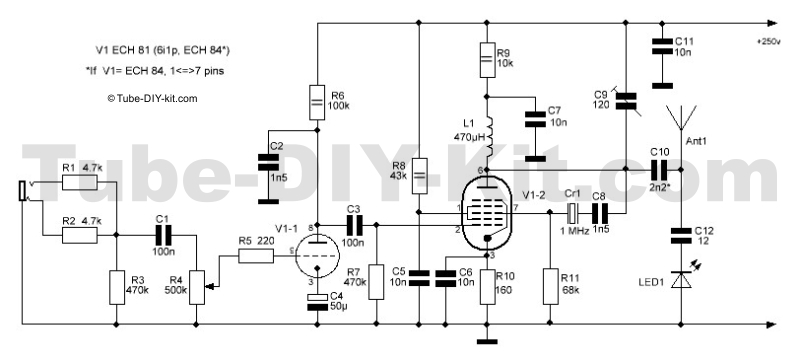
Install and solder all the parts on the board according to the circuit diagram and the board layout. While installing the electrolytic capacitors make sure the polarity is right. The filter capacitors marked on the board as Ch are not indicated on the scheme but are recommended to be installed if the transmitter works with extraneous power supplies. In our power supplies, such capacitors are already installed.
 After assembling the circuit connect the antenna to the “Ant” terminal and also the anode and incandescent voltage from the power supply. You can use a piece of one-meter or longer cable as an antenna. A properly assembled transmitter usually starts working at once. Only a tuning of the output circuit with the help of the C9 trimmer by the maximum LED1 glow. It is recommended to control the consumption of electricity by the anode cables during turning on the device for the first time. The number should not be more than 10mA while the LED1 glows. Then give the signal from the source to the AUX jack and tune the radio receiver to the frequency of the transmitter. At the end of the choose the modulation level with the R4 variable resistor and the spatial position of the transmitter’s antenna by the minimum 50Hz noise in the receiver.
If the working frequency in your region is already used by another radio station or has noises then install a capacitor with a capacity of 10-20pf under the board parallel to the R11 resistor. This will somewhat move the transmission frequency.
The transmitter can be tuned to shortwave. To do this, change the ceramic resonator Cr1 to quartz. For example, with common quartz 9.6 - 10MHz, the operating frequency will shift to a range of 31 meters. In addition to the quartz replacement, you will have to change the L1 inductance from 470μH to 20μH, the C9 trimmer should be changed to 30pf and a C10 capacity should be selected for optimal communication with the antenna. But the LED1 cannot be used as a radiation indicator at this frequency.


